
TLDR
Control rooms in broadcast studios, 911 dispatch centers, military command posts, and security operations centers depend on displays that run 24/7 without failure. This guide breaks down the hardware categories that matter most for these environments: rackmount LCD monitors (including PIP quad-screen models), video matrix switches, and multiviewer processors. We cover how to match display density, resolution, and rack form factor to each type of control room, with practical rack layout scenarios for broadcast, dispatch, military, and security operations.
Control Room Display Solutions: Rackmount LCD and Video Matrix Configurations for Mission-Critical Environments

Why Control Room Displays Are Not Standard IT Monitors
A control room display has one job: keep critical visual information visible to operators at all times, with zero tolerance for failure. That requirement separates control room hardware from standard office or data center monitors in several important ways.
24/7 operational duty. Commercial LCD panels rated for continuous operation typically carry MTBF (Mean Time Between Failures) ratings of 50,000 to 100,000 hours. For a display running around the clock, a 50,000-hour MTBF translates to roughly 5.7 years of continuous operation before a statistical failure event. Control room monitors built for this duty cycle use industrial-grade panels, ruggedized power supplies, and thermal management systems designed for enclosed rack environments where ambient temperatures run higher than a typical office.
Multi-source visibility. Operators in a 911 dispatch center or broadcast control room need to see four, eight, or sixteen sources simultaneously. Standard desktop monitors show one input at a time. Control room displays, by contrast, use PIP (picture-in-picture), PBP (picture-by-picture), and quad-view modes to tile multiple sources on a single screen, reducing the number of physical displays an operator must scan.
Rack density. Floor space in a control room is expensive and heavily planned. Rackmount LCD monitors pack display real estate into standard 19-inch rack units, eliminating the desk clutter and cable chaos that desktop monitors create. A single 8U rackmount LCD with quad-screen capability replaces four standalone monitors and their associated power, video, and USB cabling.
Core Hardware Categories for Control Room Displays
Three hardware categories form the backbone of most control room display configurations. Understanding what each one does (and where it fits in the signal chain) prevents over-engineering and budget waste.
Rackmount LCD Monitors
Rackmount monitors mount directly into standard 19-inch EIA-310 server racks. They come in several form factors:
- 1U pull-out drawer displays (typically 17 to 19 inches diagonal). These fold flat when not in use, conserving rack space. Best suited for server rooms and network operations centers where operators need occasional visual access rather than constant monitoring.
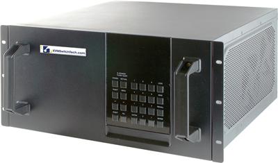
- Multi-U fixed-mount displays (4U to 10U, with screen sizes from 17 to 20+ inches). These remain visible at all times and are the standard choice for broadcast control rooms and security operations centers where operators watch feeds continuously.
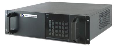
- PIP quad-screen rackmount LCDs. These combine a multi-view processor with a rackmount display in one unit, accepting four independent video inputs and displaying them in quad, PIP, or PBP layouts. They are particularly valuable in dispatch centers where a single operator needs to monitor a CAD (computer-aided dispatch) system, a mapping application, a radio log, and a surveillance feed simultaneously. KVMSwitchTech carries a full line of PIP quad-screen LCD monitors designed for exactly this use case.
- Sunlight-readable rackmount LCDs. Designed for field-deployed racks, mobile command vehicles, and military shelters where ambient light levels vary widely. These panels offer brightness ratings of 1,000 nits or higher, compared to the 250 to 400 nits typical of standard rackmount displays. Browse sunlight-readable rackmount LCD monitors for deployable and high-ambient-light environments.
Video Matrix Switches
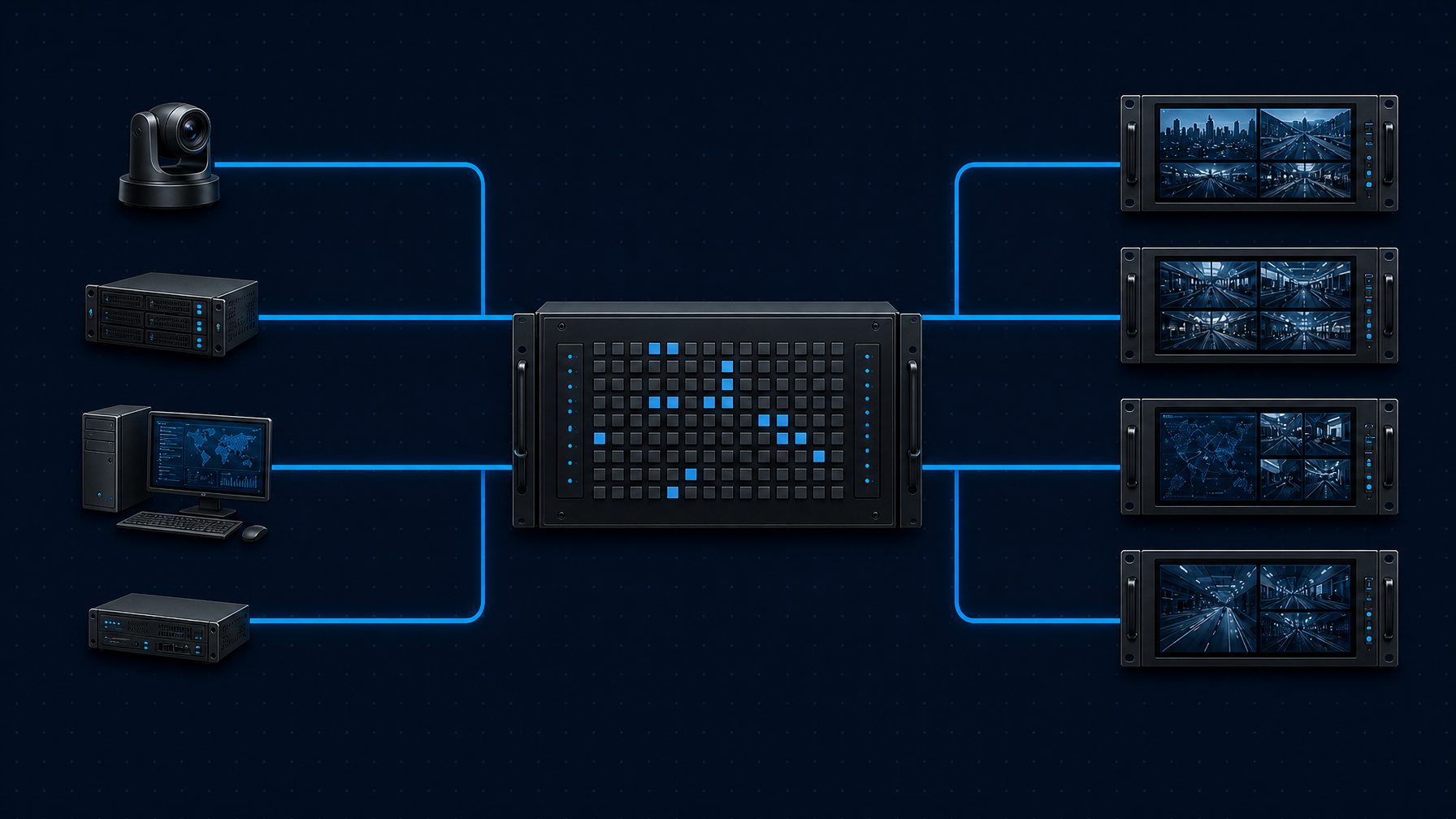
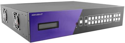
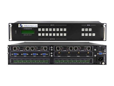
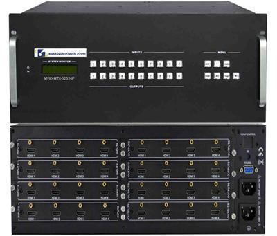
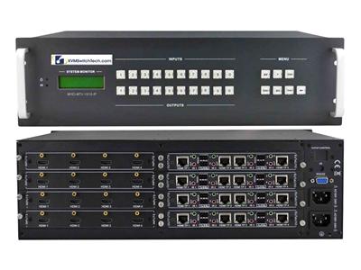
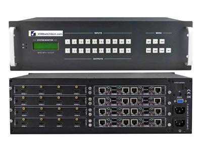
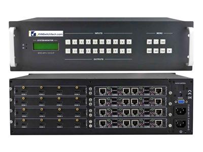
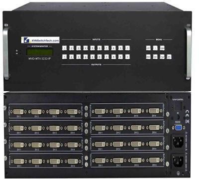
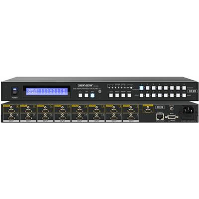
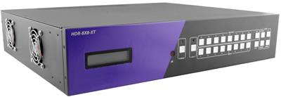
A video matrix switch sits between your sources (servers, cameras, encoders, decoders) and your displays. It routes any input to any output, allowing operators to reconfigure what appears on each screen without touching cables.
Key specifications for control room video matrix switches:
| Specification | Why It Matters in a Control Room |
|---|---|
| Input/output count (e.g., 4×4, 8×8, 16×16) | Determines how many sources and displays the system supports. A small broadcast control room might need 8×8; a large 911 center might need 16×16 or larger. |
| Video format (HDMI, DVI, SDI, DisplayPort) | Must match both the source equipment and the display inputs. Broadcast environments often require SDI support; IT-centric rooms typically use HDMI or DisplayPort. |
| Maximum resolution | 4K at 60Hz (4:4:4) is the current standard for new installations. Legacy systems may be limited to 1080p. |
| Seamless switching | Eliminates the black-screen "glitch" during source changes. Critical in broadcast where on-air feeds pass through the matrix. |
| Control interfaces (RS-232, TCP/IP, IR, front panel) | Determines how operators and automation systems interact with the matrix. TCP/IP control is essential for integration with broadcast automation or building management systems. |
| HDCP compliance | Required when routing content-protected sources (Blu-ray players, cable boxes, certain camera systems). |
Multiviewer Processors
A multiviewer processor takes multiple video inputs and composites them onto a single output, creating a tiled or windowed display on one screen. While PIP quad-screen rackmount LCDs include this capability built in, standalone multiviewer processors offer more flexibility:
- Higher input counts (8, 16, or 32 sources on a single display)
- Custom window layouts with resizable and repositionable windows
- On-screen labels, borders, and alarm indicators (UMD, or Under Monitor Display, in broadcast terminology)
- Audio metering overlays
- Redundant input failover
Standalone multiviewers pair well with large-format displays or video walls in control rooms where operators need a "big picture" overview, while rackmount LCD quad-screen units serve individual operator positions.
Rack Layout Scenarios by Control Room Type
Every control room has different operational priorities. The following scenarios illustrate how to configure rackmount displays and video matrix switches for four common environments.
Scenario 1: Broadcast Control Room
Operational profile: A broadcast control room manages live on-air production. Operators include a technical director, audio engineer, graphics operator, and producer. Each operator needs to see program output, preview output, multiple camera feeds, and graphics playback simultaneously.
Typical display configuration:
- Equipment rack (per operator position): One 8U rackmount LCD with quad-screen capability showing four key feeds (program, preview, two camera ISOs). This gives each operator an at-a-glance view without turning away from their primary control surface.
- Central monitoring wall: An 8×8 or 16×16 HDMI video matrix switch feeding a bank of rackmount multiviewers or a video wall processor. This wall shows all camera feeds, graphics channels, remote feeds, and return feeds tiled across a large display area.
- Signal format considerations: Broadcast facilities often mix SDI (from cameras and routers) with HDMI (from graphics workstations and replay servers). The video matrix switch must handle both formats or the facility must standardize on one with appropriate converters at the edge.
Rack space budget: For a six-operator broadcast control room, plan for approximately 24U to 32U of display-related equipment across one or two racks, including the matrix switch (typically 1U to 4U depending on port count), power distribution, and cable management.
Scenario 2: 911 Dispatch Center
Operational profile: A Public Safety Answering Point (PSAP) operates around the clock with dispatchers handling emergency calls. Each dispatcher position requires simultaneous visibility into a CAD system, a GIS mapping application, radio status displays, and often a surveillance camera feed from building security.
Typical display configuration:
- Per-dispatcher position: One PIP quad-screen rackmount LCD (typically 19 inches, 4U to 8U) mounted in a console-integrated rack at each workstation. The quad-screen mode tiles four sources, and PIP mode lets dispatchers enlarge one source while keeping the others visible in smaller windows.
- Supervisor overview position: A larger multi-U rackmount display or a desktop monitor driven by a multiviewer processor, showing aggregated status from all dispatch positions.
- Shared situational awareness wall: A video matrix switch (4×4 or 8×8) routes selected camera feeds, weather radar, or news broadcasts to a shared wall-mounted display visible to all dispatchers.
Reliability considerations: NENA (National Emergency Number Association) publishes standards for PSAP operations that emphasize redundancy and continuous availability (NENA Standards). Display hardware in a 911 center should support hot-swappable power supplies where available, and the facility should maintain spare rackmount LCD units for rapid replacement. Dual-input displays that accept two video sources and automatically switch to the backup on signal loss provide an additional layer of resilience.
Scenario 3: Military Command Center
Operational profile: Military command and control (C2) facilities process intelligence feeds, satellite imagery, tactical communications, and video teleconference (VTC) sessions. Security classification levels may require physical separation of networks, meaning displays connected to classified and unclassified systems cannot share signal paths.
Typical display configuration:
- Per-operator position: Sunlight-readable rackmount LCDs (for deployable or field environments) or standard multi-U rackmount displays (for fixed installations). Each operator position may require two physically separate displays, one for each network classification level.
- Common operational picture (COP) wall: A large video matrix switch (16×16 or larger) routes selected intelligence feeds, battle tracking displays, and VTC sessions to a shared display wall. In classified environments, the matrix switch itself must meet security requirements, and any KVM switching between networks typically requires NIAP-validated secure KVM switches rather than standard consumer-grade matrix switches.
- Rack hardening: Military-spec racks may require shock and vibration isolation. Rackmount LCD displays selected for these environments should meet relevant MIL-STD requirements for shock (MIL-STD-810) and EMI/EMC (MIL-STD-461). Manufacturers like Winmate produce rack mount defense display models specifically designed for these conditions (Winmate).
Scenario 4: Security Operations Center (SOC)
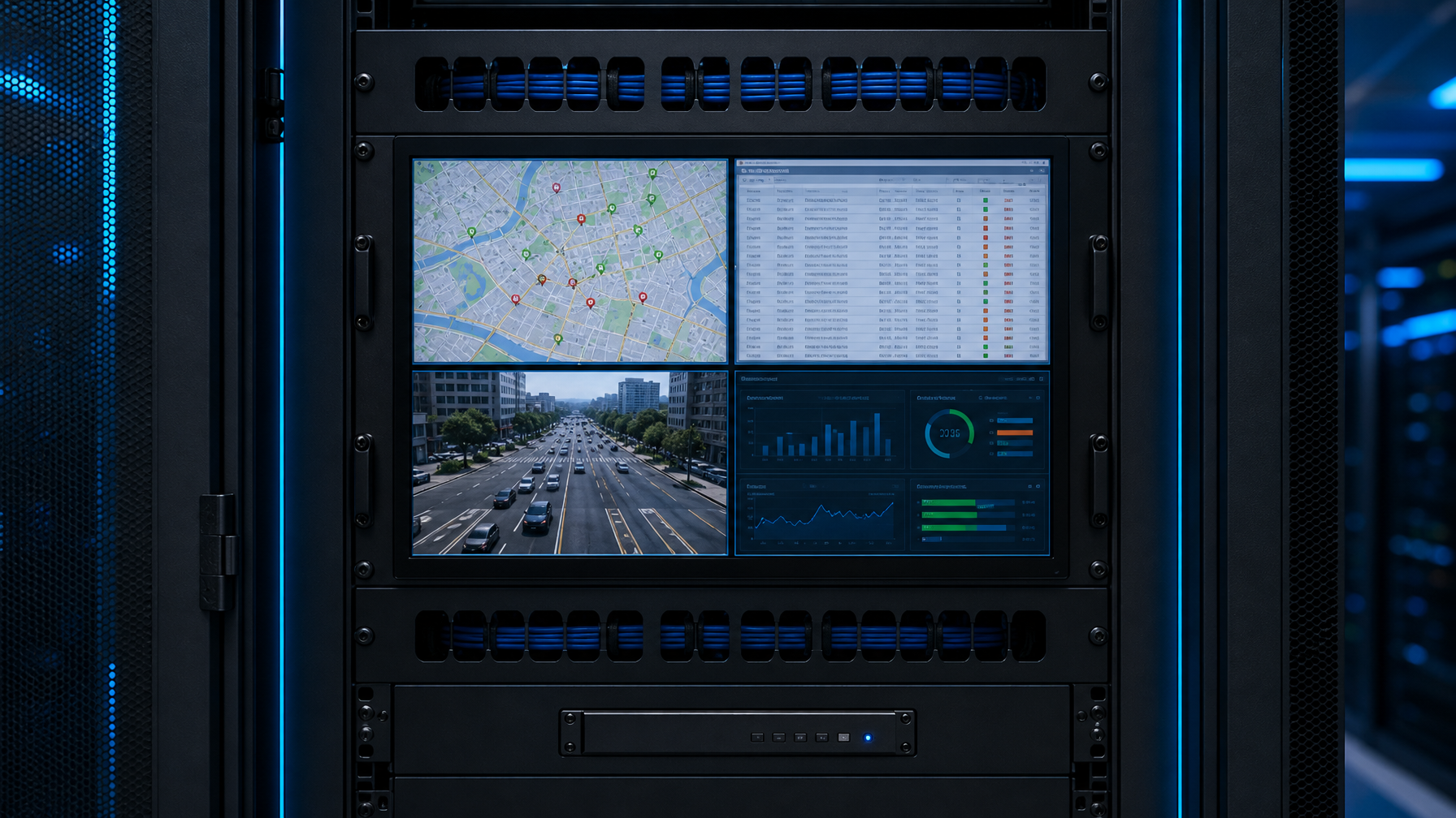
Operational profile: A security operations center monitors physical security cameras, access control systems, alarm panels, and sometimes cybersecurity dashboards. The operator count is typically smaller (two to six), but the source count is very high (dozens to hundreds of camera feeds).
Typical display configuration:
- Operator positions: PIP quad-screen rackmount LCDs showing the four highest-priority camera feeds or system dashboards per operator. Operators cycle through camera groups using the quad-screen's input switching, or they use the video matrix switch to pull specific cameras onto their display.
- Video wall: A large HDMI matrix switch (16×16 or 32×32) routes camera feeds to a video wall composed of multiple displays. The matrix switch allows operators to reassign any camera to any position on the wall in response to an alarm or incident.
- Integration with VMS: The video management system (VMS) software typically runs on dedicated servers, with each server outputting one or more HDMI or DisplayPort feeds. These feeds connect to the matrix switch inputs, and the matrix routes them to operator displays and the video wall. This architecture keeps the VMS server hardware in a separate server room while delivering video to the SOC display wall over structured cabling.
How to Specify Control Room Displays: A Decision Checklist
Use this checklist when specifying rackmount LCD monitors and video matrix switches for a control room project.
1. Count Your Sources and Displays
List every video source that operators need to see (servers, cameras, encoders, external feeds) and every display position (operator monitors, shared walls, supervisor stations). This count determines the minimum matrix switch size. Add 20% to 30% headroom for future expansion.
2. Identify the Video Format
Standardize on a single video format where possible. HDMI is the most common choice for new IT-centric control rooms. Broadcast facilities may need SDI or a mix of SDI and HDMI. If you must mix formats, plan for converters at the matrix switch inputs or select a matrix switch that accepts multiple format types.
3. Set the Resolution Requirement
For new installations in 2026, 4K at 60Hz (3840×2160) is the recommended baseline. It provides enough pixel density for quad-screen display modes where each quadrant effectively runs at 1080p. If budget is constrained, 1080p rackmount LCDs still serve well for single-source operator positions, but they limit the usefulness of quad-screen tiling because each quadrant drops to 960×540.
4. Determine the Duty Cycle
Is the control room staffed 24/7, or does it operate during business hours only? Continuous-duty environments require displays rated for 24/7 operation, with MTBF ratings above 50,000 hours and panel technology designed to resist image retention (burn-in). IPS panels are generally preferred over VA or TN panels for control room use because they offer wider viewing angles and better color consistency across the screen.
5. Measure the Rack Space Budget
Calculate available rack units. A common mistake in control room design is underestimating the rack space consumed by display equipment. Remember to account for:
- The display itself (1U to 10U depending on type)
- Video matrix switch (1U to 4U)
- Multiviewer processors (1U to 2U each)
- Cable management panels (1U between each major component)
- Power distribution (1U to 2U)
- UPS or conditioned power (variable)
6. Plan for Control and Automation
Determine how operators will control the matrix switch and display layouts. Options include:
- Front-panel buttons: Simple, no network dependency, but limited to basic source selection.
- RS-232 serial control: Integrates with broadcast automation systems and Crestron/Extron control processors.
- TCP/IP (web GUI or API): Enables remote control, scheduled source changes, and integration with facility management software.
- IR remote: Convenient for small rooms, but impractical for large operations where operators need instant, repeatable routing changes.
7. Budget for Redundancy and Spares
Mission-critical control rooms should maintain at least one spare rackmount LCD display and, if the budget allows, a backup matrix switch or a matrix switch with redundant power supplies and fans. The cost of a spare display is trivial compared to the operational impact of a blank screen during a live broadcast or an active emergency dispatch.
Common Mistakes in Control Room Display Projects
Overbuilding the video wall, underbuilding the operator positions. A flashy 4×4 video wall impresses visitors, but operators spend most of their time looking at their own workstation displays. Investing in high-quality rackmount LCDs with quad-screen capability at each operator position delivers more operational value per dollar than adding extra panels to the video wall.
Ignoring viewing distance and pixel density. A 4K display at 20 feet offers no meaningful resolution advantage over 1080p. Match the display resolution to the actual viewing distance. Rackmount LCDs at operator positions (viewed from 2 to 4 feet) benefit significantly from 4K resolution, especially in quad-screen mode. Shared wall displays viewed from 10 to 20 feet can often use 1080p without perceptible quality loss.
Failing to standardize video formats. A control room that mixes HDMI, DVI, SDI, and VGA sources across different eras of equipment creates a converter and adapter nightmare. When upgrading, standardize on one format (HDMI for most applications, SDI for broadcast) and convert legacy sources at the edge rather than accumulating adapters throughout the signal chain.
Skipping cable management. A 16×16 matrix switch with all ports populated generates 32 video cables, 32 potential USB or control cables, and associated power cables. Without structured cable management (horizontal cable managers, vertical cable trays, proper bend radius compliance), troubleshooting becomes nearly impossible, and accidental cable disconnections cause outages.
No remote management plan. Control rooms in government and military facilities may be physically remote or access-restricted. Specifying matrix switches and displays with TCP/IP management, SNMP monitoring, or web-based configuration interfaces allows IT staff to diagnose and reconfigure display routing without physical access to the rack.
Putting It All Together: A Sample 911 Dispatch Center Build
To illustrate how these components work together, here is a representative rack configuration for a six-position 911 dispatch center:
Per-dispatcher rack (6 racks total):
| Component | Rack Units | Purpose |
|---|---|---|
| PIP quad-screen rackmount LCD (19 inches) | 8U | Primary operator display; four simultaneous sources (CAD, GIS, radio, camera) |
| Cable management panel | 1U | Route video and USB cables cleanly |
| KVM switch (if controlling multiple PCs) | 1U | Switch keyboard/mouse between CAD workstation and secondary systems |
| Total per position | 10U |
Central equipment rack (1 rack):
| Component | Rack Units | Purpose |
|---|---|---|
| 8×8 HDMI video matrix switch | 2U | Route shared sources (weather, news, situational cameras) to dispatcher displays and wall |
| Multiviewer processor | 1U | Composite supervisor overview onto a single display |
| Network switch (for IP-based control) | 1U | TCP/IP control of matrix switch and KVM units |
| UPS | 4U | Battery backup for display equipment |
| Cable management and patch panels | 4U | Structured cabling |
| Total central rack | 12U |
This configuration consumes approximately 72U across seven racks (60U for six dispatcher positions plus 12U for central equipment). It provides each dispatcher with four simultaneous video sources, gives the supervisor an aggregated overview, and allows shared situational awareness feeds to be routed to any position or to a common wall display.
What to Evaluate Next
Once you have defined the source count, video format, resolution, and rack space for your control room project, the next step is to evaluate specific rackmount LCD models (standard, quad-screen, and sunlight-readable) and video matrix switches (HDMI, DVI, and SDI) that match your specifications. Manufacturers like Austin Hughes, ATEN, and Eaton Tripp Lite offer product lines specifically designed for control room environments, with industrial-grade panels, extended warranties, and 24/7 duty-cycle ratings.
When comparing models, pay close attention to three factors that spec sheets sometimes obscure: the actual panel type (IPS vs. VA vs. TN), the native resolution versus the supported input resolution (these are not always the same), and the control interface options (RS-232, TCP/IP, or both). These details determine whether a given display will integrate smoothly into your control room architecture or create ongoing operational friction.
Frequently Asked Questions
What is a control room display?
A control room display is a monitor designed for continuous operation in environments like broadcast studios, 911 dispatch centers, military command posts, and security operations centers. These displays are built for 24/7 duty cycles, offer multi-source viewing modes (PIP, quad-screen), and mount in standard 19-inch server racks.
What is the difference between a rackmount LCD and a desktop monitor in a control room?
A rackmount LCD mounts directly into a standard server rack, saving desk space and simplifying cable management. It is typically rated for continuous 24/7 operation, while most desktop monitors are rated for 8 to 12 hours of daily use. Rackmount LCDs also frequently include multi-input PIP or quad-screen modes that desktop monitors lack.
How does a video matrix switch work in a control room?
A video matrix switch connects multiple video sources (servers, cameras, encoders) to multiple displays. Any input can be routed to any output, allowing operators to change what appears on each screen without physically moving cables. Control is handled through front-panel buttons, RS-232 serial commands, TCP/IP web interfaces, or IR remotes.
What resolution should control room displays use in 2026?
For new installations, 4K (3840×2160) at 60Hz is the recommended standard. In quad-screen mode, a 4K display renders each quadrant at 1920×1080, maintaining full HD quality per source. For shared wall displays viewed from a distance of 10 feet or more, 1080p remains acceptable.
How many rack units does a typical control room display setup require?
A single operator position with a quad-screen rackmount LCD, cable management, and a KVM switch occupies approximately 10U. A central equipment rack with a video matrix switch, multiviewer processor, network switch, UPS, and cable management uses 10U to 15U. Total rack space for a six-operator control room is approximately 72U across seven racks.
Do control room displays need special power protection?
Yes. Rackmount displays and video matrix switches in mission-critical control rooms should be powered through an uninterruptible power supply (UPS) with surge protection. A display failure during a live broadcast or an active emergency dispatch is not recoverable, so battery backup that provides at least 15 to 30 minutes of runtime allows for generator switchover or graceful shutdown.